Senior Design Capstone
For my senior design project, I worked with a team of four people to optimize a hydrofoil stabilizer design, validate the new design with CFD simulations, and manufacture the hydrofoil stabilizer for application testing. Scroll and click through the images and videos below to view the semester long project.
You may be asking yourself: "What is hydrofoiling?"
The video on the left is a demonstration from our sponsor company, Cabrinha, showing the type of hydrofoils that our project aimed to optimize. The smaller rear wing is called the stabilizer, and this particular foil is the wing we chose to design, validate, manufacture, and test.
Looking at the larger picture, our team's background knowledge in sailing propelled us to work on hydrofoils due to their prevalence in the marine transportation industry. The video on the right highlights a potential use of hydrofoils for ferries, in addition to container ships, small crafts, and other boats. The foils lower fuel consumption, decrease travel time, and improve overall efficiency. With this big picture idea in mind, our project focused on designing, manufacturing, and running CFD validations for an optimized stabilizer design.
Problem Statement
Cabrinha has asked us to optimize their hydrofoil stabilizer to reach a given lift while reducing drag. We will maintain a constant, given area.
The Design Process
CAD Modeling
Based on a benchmark stabilizer design from our sponsor (first image below), each team member made their own changes aimed at reducing drag and reaching or improving the original lift value. Four separate CAD models are shown below in the second image. My design, called Batman, focused on curving the trailing edge, increasing the chord line of the airfoil shape, and sweeping back the leading edge. The thought process behind these changes was that increasing the chord length would improve lift, yet this would would add more weight and surface area to the foil. As a result, I curved the trailing edge to reduce weight and help aerodynamic performance by reducing induced drag. I also swept the leading edge back at a greater rate to help minimize wave drag and increase lateral stability. The third image below displays the final CAD design. After a discussion with our sponsor, key elements from each design proposal were incorporated into a single stabilizer.
These features include:
-
a curved trailing edge
-
a smoother swept back leading edge
-
a new NACA 2310 airfoil shape
-
higher angled wingtips
 |  |
|---|---|
 |

Prototyping
For a mid-semester deliverable, our team 3D printed an ABS (Acrylonitrile Butadiene Styrene) prototype of the initial benchmark design and our optimized design. However, the stabilizer is about 40 cm in length and the Stratasys printer bed (even in a diagonal direction) was a few inches too small to print the entire foil. As a solution, I proposed slicing the stabilizer at a section along the wing and printing a male and female part that could be glued and attached together after printing. We ended up following this idea and after sanding and glueing, other teams could not tell the stabilizer used to be two pieces.
 |  |
|---|---|
 |
Computational Fluid Dynamics (CFD)
From my internship during the summer of 2021, I worked with the CFD software Ansys Fluent and applied this skill to initial CFD simulations for the stabilizer designs. I spearheaded this task among my team and we showed the results to our sponsor to help validate a few of the design choices we made for the optimized stabilizer. Later on in the semester, our team began to use Simulia software from Dassault Systems as this program was much easier to work with and our aerodynamics professor could offer advice on setup issues.
The graphs above show the aerodynamic parameters for the coefficient of lift and drag plotted against angle of attack. The ratio of the lift and drag for angle of attack is also shown, which the most basic measurement of aerodynamic efficiency.
 |  |
|---|
1st Set of Plots: Benchmark CFD Results
2nd Set of Plots: Final Design CFD Results (click the next image)
Analysis
Based on the CFD results, the new stabilizer design produced both a higher lift and drag compared to the original design when looking at the line of best fit for both plots. However, the ratio between the lift to drag coefficients was optimized as the stabilizer had a higher ratio at an angle of attack of five degrees. This demonstrates the new design's 35.7% increase in aerodynamic efficiency.
Prototype Testing in Oregon State University's Wave Tank
With immense gratitude to our faculty sponsor, Bryony Dupont, our team tested the 3D printed prototypes at Oregon State University's wave tank. Although sensors were unavailable, check out the cool video of the new stabilizer being towed through water!
Manufacturing
Mold for Carbon Fiber Layup
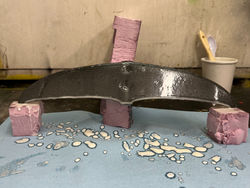
For the final product, we created a positive and negative wood mold out of MDF (medium density fibreboard) to layup carbon fiber. To cut the mold, we learned how to use a ShopBot CNC to carve the stabilizer impression created in SolidWorks. The images below show a practice foam mold we made before cutting the final mold in MDF. The machine required a huge learning curve, and this process stressed the importance of budgeting time for machining mistakes and uncontrollable errors.
 |  |
|---|---|
 |  |
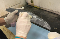
Carbon Fiber Layup
For the last few manufacturing steps, we did a wet layup of carbon fiber where we coated a carbon fiber sheet with resin and cut layers of the foil outline to spread over the positive and negative mold. To fill the space between the top and bottom sheets, we spread epoxy micro-balloons over the mold and clamped the halves together. The resin took around 24 hours to settle and harden and then post processing involved sanding and applying another coat of resin to smooth over the seams of the leading and trailing edge. A release agent was not applied to the mold, so the MDF mold was unfortunately not able to be used again. However, in future iterations the stabilizer could easily be reproduced with another mold!
 |  |
|---|---|
 |  |
 |  |
 |  |
Finished Product & Testing
Testing!
The image below shows the final carbon fiber product attached to the fuselage body. One of our group members can hydrofoil and was able to ride the new stabilizer, so it was rewarding knowing a product we designed and built was able to be used in the field.
 |  |
|---|
Presentation
Demonstration
On December 6th, 2021 we presented to the Mechanical Engineering department and other capstone groups. The poster below displays key milestones from the project. The most surprising takeaway from the presentation was the audience's interest in the materials and manufacturing process, so it helped to have the prototypes available for touching and to physically show the design changes compared to the benchmark stabilizer.

Reflections
-
Budgeting time for machining errors is important
-
Learned new skills in ShopBot CNC and carbon fiber layup
-
Learned how to communicate with sponsors effectively
-
Working in a group to maximize individual strengths is a successful strategy
Acknowledgements
Team
Alexander Fasolo, Tufts University
Sam Merson, Tufts University
Talia Toland, Tufts University
Sponsors
Brodie Sutherland, Cabrinha Kites
Bryony DuPont, Oregon State University/Tufts University
Appendix
-
Brainstorming of optimization ideas
-
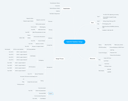
Mind map of stakeholders, team, resources, and the design process (zoom in)
-
Bill of Materials
 |  |
|---|---|
 |